Solution · Owned venture
Solar Tracker Platform
Connect the lifecycle of a tracked photovoltaic system from engineering and control through telemetry, a digital twin and operated digital components.
Physical prototypes and simulation are operational; long-term physical validation is ongoing.
- 1
Engineering
Design mechanics and control logic
- 2
Prototype
Test physical behaviour
- 3
Telemetry
Capture measurement and condition data
- 4
Digital twin
Compare simulation and measurement
- 5
Operate & validate
Improve the model and system progressively
Five connected steps: engineering, prototype, telemetry, digital twin, and operations and validation.
Business and technical question
How can a tracking system be designed, tested and operated without confusing the model with physical reality?
The platform keeps design, control logic, measurement data and operations in one traceable system. Simulation and physical measurement are reported separately and compared for progressive calibration.
What the approach enables
- 01Compare design alternatives before changing the hardware
- 02Use telemetry for system visibility and model calibration
- 03Evolve control, user application and platform together
System architecture
Seven connected layers — from the physical tracker to continuous validation.
The architecture summarises the documented scope of the prototype and its digital components. It does not describe an already industrialised series configuration.
Seven connected layers: physical tracker and mechanics, controller and firmware, IoT telemetry, digital twin and simulation, user application, platform operations, and continuous validation.
Physical Tracker & Mechanics
Tracking mechanics and physical prototypes form the real-world system layer.
Controller & Firmware
Control logic and firmware translate the tracking concept into movement.
IoT Telemetry
The prototype captures position, yield, environmental and system-state data.
Digital Twin & Simulation
The browser model simulates alternatives while keeping model values and measurements separate.
User Application
Configuration, monitoring and analysis connect people with the system.
Platform Operations
Defined deployments, monitoring and backups support the digital components.
Continuous Validation
Telemetry supports progressive calibration while long-term physical validation continues.
Visual evidence
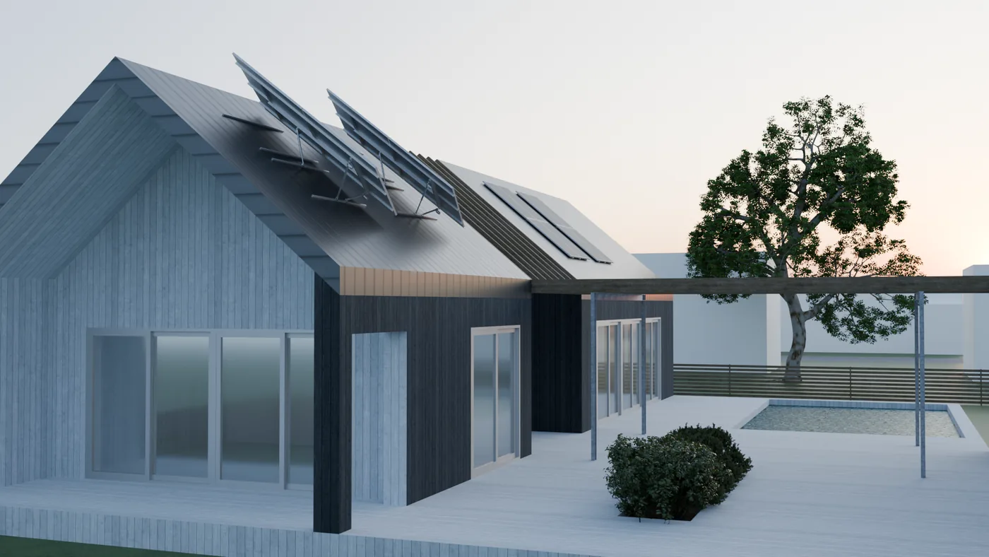
A visual with a clear claim boundary.
The visual explains the intended application context. Documented evidence for the physical prototype and its current validation status is provided in the case study.
Interactive digital twin
Explore the model in your browser.
The first-party simulation illustrates system behaviour and alternatives through a simplified technical model. It is not a yield guarantee for a specific site.
Connected capabilities
One system across engineering, data and operations.
The documented scope focuses on the prototype and its digital components. Further industrialisation stages are not presented as already delivered.
01
Engineering & control
Design the tracking mechanics, control logic and firmware-adjacent development together.
Documented scope
02
IoT & telemetry
Capture position, yield, environment and system state from the prototype through to analysis.
Documented scope
03
Digital twin
Keep simulation and real measurements separate and make them comparable for design decisions.
Documented scope
04
Platform & operations
Provide the digital components through defined delivery and operating processes.
Documented scope
Solution lifecycle
From design to a learning system.
The solution path connects the physical product and digital platform without presenting a prototype as a completed series rollout.
01
Engineering
Design mechanics and control logic
02
Prototype
Test physical behaviour
03
Telemetry
Capture measurement and condition data
04
Digital twin
Compare simulation and measurement
05
Operate & validate
Improve the model and system progressively
Five connected steps: engineering, prototype, telemetry, digital twin, and operations and validation.
Documented practice
What is evidenced today.
The existing project record separates role, status, results and limitations. This solution page does not replace that evidence; it leads to it.
Documented evidence
- Physical prototypes have been built and are delivering measurement data.
- The simulation model is operational and the browser-based digital twin is publicly accessible.
- The digital components run with defined deployment, monitoring and backups in an environment operated by Somos-Co.
Read the Solar Tracker case study
Role, status, technical implementation, evidence and limitations in detail.
Explore Digital Delivery
The technical capability behind the application, IoT, platform and operations.
Claim boundaries
Beta is a status, not a finished series promise.
The solution is presented at its actual maturity. Simulation and initial measurements are not extended into general product promises.
- Long-term physical validation across complete annual cycles is ongoing.
- No yield is guaranteed for a specific site.
- Series manufacturing, area-wide rollout, installation, commissioning and maintenance are not claimed as already realised solution modules.
- This page avoids the dual-axis designation while that claim remains under review.
Solar Tracker solution
Which design or integration question would you like to test?
Describe the site context, intended outcome and existing technical components. Together, we clarify which part of the solution approach is relevant.